A manager that sets the envelope. A module that holds it.
Two coordinated layers for closed-loop AI rack power orchestration — ORv3 / ORW today, designed for Mt Diablo ±400 VDC / 800 VDC.
Facility-level layer that sets the power envelope for each rack from grid conditions and site policy, and records per-rack event evidence for the site's compliance reporting.
INTERFACES
- Redfish API — telemetry ingestion
- Site EMS / point-of-interconnection data — grid state and policy
- POM interface — rack envelope to each Module
Interface contributed to OCP Rack & Power as POM
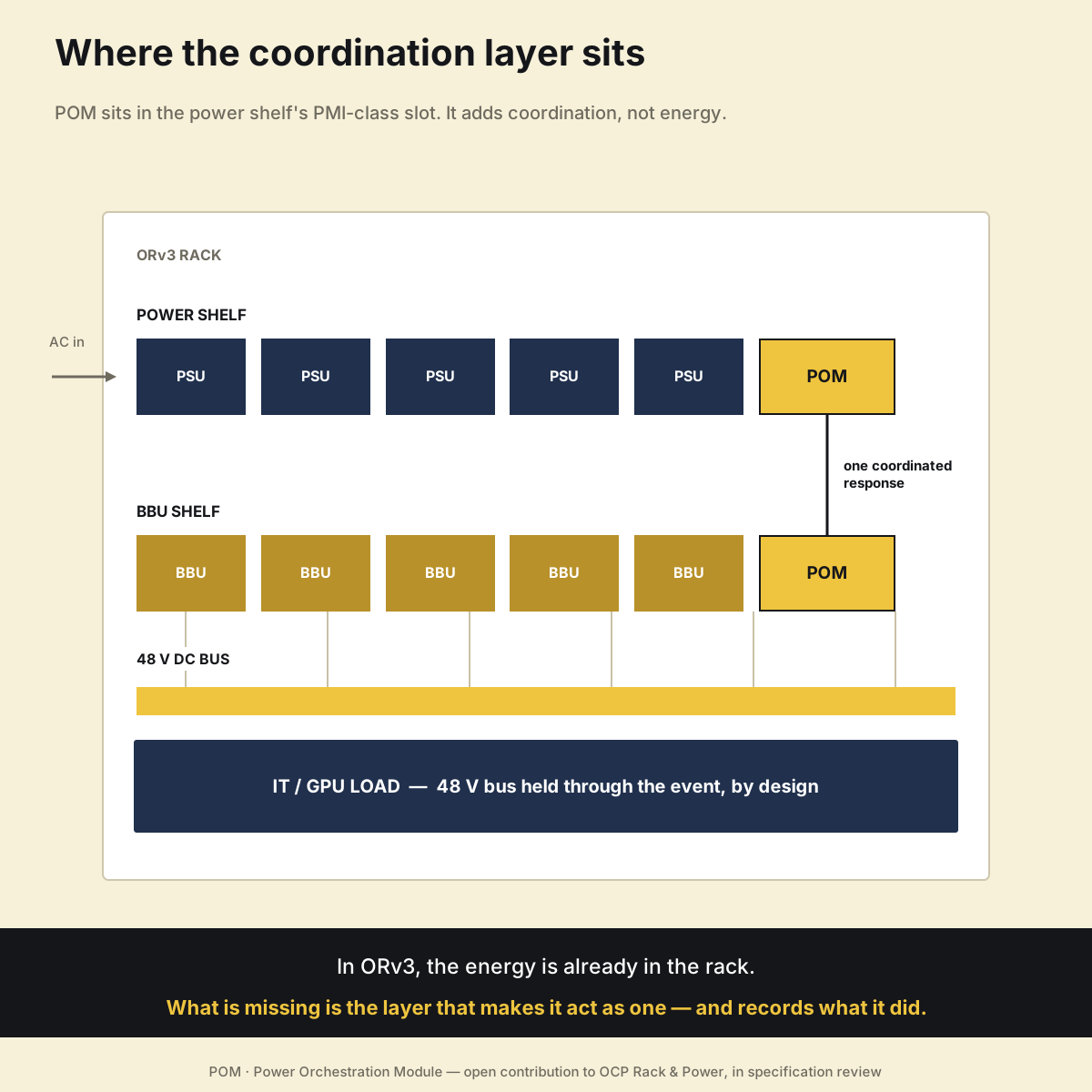
Rack-mounted module that coordinates BBU discharge and PSU output inside the ORv3 power shelf. Installs in the PMI-class slot with its own control plane, and keeps operating autonomously if the facility layer is unreachable.
INTERFACES
- ORv3 power shelf, PMI-class slot
- SMBus + PMBus control
- Real-time BBU + PSU coordination
Implements POM — in review, OCP Rack & Power
Who controls what
- The Manager decides the envelope.
- The Module executes locally.
- Fast protection never depends on the network or the facility controller.
- Compliance is measured for the whole site at its grid connection point.
CONTROL LOOP
How XMight's POM implementation responds
ARCHITECTURE
Set the envelope, coordinate the rack, prove it.
XMight's POM implementation sits between the data center EMS and the ORv3 rack. The diagram below shows POM (Power Orchestration Module) — XMight's open contribution to OCP Rack & Power — and the two-layer architecture of the XMight POM Module and POM Manager.
Built on ORv3 / ORW racks today. POM is topology-agnostic and designed for Mt Diablo ±400 VDC and NVIDIA 800 VDC sidecar architectures, where one power rack feeds several IT racks and recovery concentrates on the power rack.
AI racks are provisioned with headroom for transient peaks — compute capacity held back. Coordinated BBU discharge absorbs the spikes instead, so the reserve can shrink: XMight's OCP 2025 Active BBU paper models a 25–35% lower peak-to-average ratio. Throttling isn't eliminated; it's made smaller and continuous.
Source: XMight, The Active BBU: Dynamic Power Orchestration for Stable and Efficient ORv3 AI Racks, OCP Global Summit 2025 (Table I).
VOLTAGE EVENT RESPONSE
What happens to an ORv3 rack — with and without POM.
Simulated voltage events, four traces each. Left: conventional ORv3 rack power. Right: the same event with the XMight POM Module coordinating BBU discharge and PSU output.
Without POM, the PFC trips within milliseconds and a PSU cold start takes 6–17 seconds (OCP DCF LVDC white paper v1.1) — far beyond the 2-second PFAPR window. With POM, the XMight POM Module detects the event locally, coordinates BBU discharge to hold the 48 V busbar, and the PSUs ramp back inside the 2-second window in simulation. Same distributed-power architecture, with an added coordination path.
Simulated for illustration; not a measurement of a specific product.
POWER FLOW
From GPU transient to grid-visible load.
XMight's POM implementation is designed to absorb the transient inside the rack, before it reaches the site's grid connection.
INDUSTRY ANALYSIS
Four gaps that close-the-loop control must address.
Mapped against current OCP ORv3 specifications. Each gap belongs to a different leaf-spec owner — none can be closed by a single vendor or a single spec change. POM defines the coordination layer; compatible PSU, BBU and PMI implementations expose the capabilities it needs.
PSU PFC low-voltage behaviour
ORv3 PSU operates 180–305 V AC; specification permits derating between 180–198 V. Below 180 V (~0.65 p.u. of 277 V), PFC shuts off in approximately 20 ms with 20 ms holdup. Under ERCOT NOGRR 282 the load must already ride through deeper sags, and from 1 January 2028 it must keep consuming power down to 0.50 p.u.
PSU controller power-on delay
PSU controller loses power on AC drop; on restart the ORv3 PSU specification adds a randomized 0–5.5 s power-on delay for inrush staggering, on top of a cold-boot of several seconds. ERCOT's PFAPR window is 2 seconds from voltage recovery — current behaviour cannot meet it.
BBU trigger condition
BBU Module 1.4 §4.5 specifies discharge trigger at busbar < 48.5 V for 2 ms. This covers full AC loss but does not provide coordinated voltage-sag support.
PMI interface scope
PMI Specification 1.0 §2 defines pass-through monitoring only. No write commands, no open rack-level read-write coordination path is currently defined.
Closing the four gaps takes the POM coordination layer plus compatible PSU, BBU and PMI behaviour — which is why POM is proposed as an open OCP interface.
OCP INTEGRATION
POM: the open interface the XMight POM Module implements.
Our OCP contribution defines POM — a new module class in the PMI-class slot with its own control plane — together with the coordinated PSU, BBU and PMI amendments that grid ride-through needs: PSU input envelope, controller keep-alive and fast resume; BBU sag-triggered discharge; a read-write coordination path in PMI. The table maps each leaf spec to the requirement it must meet.
| Specification | Version | ERCOT requirement | Status |
|---|---|---|---|
| Open Rack V3 Base | 1.0 | VRTFRT |
Gap identified |
| Power Shelf | 1.0 | VRTPFAPR |
Gap identified |
| 48V PSU | 1.0 | VRTPFAPRFRT |
Gap identified |
| PMI | 1.0 | VRTPFAPR |
Gap identified |
| BBU Shelf | 1.1 | VRTPFAPR |
Gap identified |
| BBU Module | 1.4 | VRTPFAPR |
Gap identified |
| Modbus Register Map | 0.73 | PFAPR |
Under review |
The Active BBU: Dynamic Power Orchestration for Stable and Efficient ORv3 AI Racks
Presented at OCP Global Summit 2025
This paper describes the Active BBU architecture — the technical foundation of POM — and its role in rack-level post-fault recovery while reclaiming compute headroom traditionally reserved for transient buffering.